Commercial Hydronic Radiators
Model TT
Low Surface Temp: Radiant Baseboard

low surface temperature radiators – Thermotouch®:
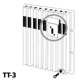
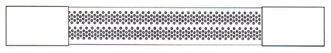
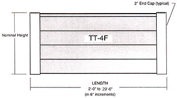
Runtal Thermotouch® (TT) low surface temperature radiators where surface temperature is a concern, such as schools, day cares, hospitals, or public spaces. The models are perimeter systems with a second layer of inactive tubes in front of the heating tubes. This reduces the front panel temperature by as much as 40 to 60°F less than the average water temperature. Due to their physical configuration, these units are both radiant and convective.

Product Specifications
General:
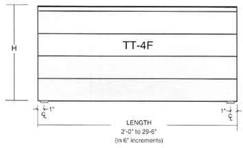
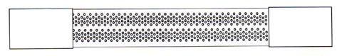
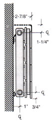
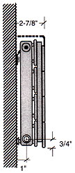
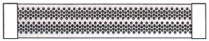
Provide Runtal ThermoTouch radiation of the lengths and in locations as indicated, and of capacities, style and having accessories as scheduled. The ThermoTouch radiation shall be of one-piece all-welded steel construction, consisting of active flattened hot water heating tubes welded to headers at each end, plus a front set of inactive tubes for added thermal protection, with a total depth of no more than 2-3/4″. The ThermoTouch radiator shall include an integral heavy gauge (0.09” minimum) all-welded perforated flat top grille which covers the entire radiator from the front inactive tubes to within 1/4″ of the wall.
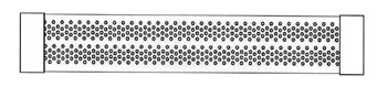
ThermoTouch models to have steel corrugated fins welded to both sides of the active water tubes to increase the convective output of the unit. There shall be no less than 32 fins per foot. Fins shall start within 1” of the headers, and shall be spot-welded three times per tube.
The headers shall include all necessary inlet, outlet and vent connections as required. Standard connection sizes are ó” NPT tapered thread for supply and return piping, and 1/8” for the vent connection. Internal baffling is provided where required for proper water flow.
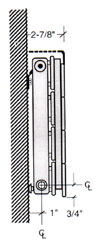
ThermoTouch panels shall be available in lengths from 2’-0” to 29’-6” in six inch increments without the need for splicing. The panel radiation shall be capable of being mounted to typical stud wall construction without additional blocking or strapping. Appropriate wall mounting brackets shall be provided with the radiation.
Pressure ratings for the radiation shall be as follows:
STANDARD: Working pressure-56 PSI maximum, Test Pressure-74 PSI maximum
OR
HIGH: Working pressure-128 PSI maximum, Test Pressure 184 PSI maximum
ThermoTouch expansion shall not exceed 1/64” per foot of radiation at 215ºF. The installer shall provide adequate expansion compensation for each radiator.
ThermoTouch radiation shall be cleaned and phosphatized in preparation for the powder coat finish. The radiation is then finish painted with a gloss powder coat finish, for a total paint thickness of 2-3 mils (0.002” – 0.003”). The color shall be selected form the Runtal’s standard colors, or optional colors shall be available at and additional cost. ThermoTouch trim covers shall be furnished with the radiation to provide a finished installation.
Manufacturer:
ThermoTouch radiation shall be manufactured in the USA by Runtal North America, Inc.
Warranty:
All ThermoTouch radiators will have a five year standard limited warranty.
OPTIONAL ITEMS WHICH MAY BE ADDED TO THE SPECIFICATION:
The radiation manufacturer shall provide combination shutoff valve/union fitting of less than two inches in width for the supply and return to each panel radiator, to be field installed by others.
Runtal-Flex connectors shall be used where appropriate to provide expansion compensation for the radiators.
Specifications
|
|
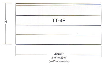
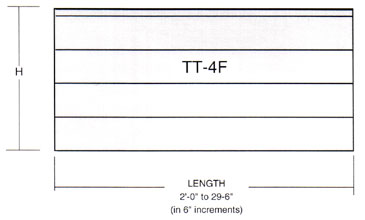
Runtal Thermotouch ® (TT) panel radiators are designed for low surface temperature applications such as schools and hospitals. The panels are finished in a gloss powdercoat, and are available in many standard colors and over 100 optional colors. These panels are made in lengths from 2’-0” to 29’-6”, and heights from 6” to 12”. Standard piping connections are 1/2” NPT for inlet and outlet piping, and 1/8” NPT for vents (3/4” NPT inlets and outlets are available by special order). For more complete TT specifications, please refer to the Runtal technical pages. |
BTUH/FT RATINGS
| Energy efficient as well as space saving, TT panels are both radiant and convective. These panels provide more comfort at a lower room temperature than convective heaters. Various average water temperatures (AWT) are shown here for convenience, but for more specific conditions use the appropriate correction factor with the 215°F rating. Please see the technical pages for the correction factor best suited to the design conditions. |
|
||||||||||||||||||||||||||||||
Mounting Systems
|
|
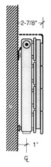
Wall mounting with a continuous mounting system (brackets included) is standard on all TT panels. Please see the TT technical pages for more complete mounting details. |
BTUH/ft Ratings
| Energy efficient as well as space saving, TT panels are both radiant and convective. These panels provide more comfort at a lower room temperature than convective heaters. Various average water temperatures (AWT) are shown here for convenience, but for more specific conditions use the appropriate correction factor with the 215°F rating. Please see the technical pages for the correction factor best suited to the design conditions. |
|
||||||||||||||||||||||||||||||
Heating Capacity
Energy efficient as well as space saving, TT panels are both radiant and convective. These panels provide more comfort at a lower room temperature than convective heaters. Various average water temperatures (AWT) are shown here for convenience, but for more specific conditions use the appropriate correction factor with the 215°F rating. Please see the technical pages for the correction factor best suited to the design conditions.
| BTUH/ft Ratings @ 65°F EAT | |||||
| MODEL | HEIGHT inches | DEPTH inches | 215°F | 180°F | 140°F |
| TT-2 | 6.0 | 3.3 | 870 | 610 | 349 |
| TT-3 | 9.0 | 3.3 | 1120 | 784 | 451 |
| TT-4 | 12.0 | 3.3 | 1360 | 952 | 544 |
Piping Options
Piping Options
A Type Piping
top view – shown with 2″ end caps
|
|
front view |
|
Model |
Nominal |
|
TT-2F |
6″ |
Piping Options
B Type Piping
top view – shown with 12″ end trims
|
|
front view |
|
Model |
Nominal |
|
TT-2F |
6″ |
Piping Options
C or D Type Piping
top view – shown with 12″ end trims
|
|
front view |
|
Model |
Nominal |
|
TT-2F |
6″ |
Pressure Drop: Opposite End
Model Type ThermoTouch
Pressure Drop: Opposite End
RADIATOR PRESSURE DROP – FOOT OF HEAD PER RADIATOR
![]()
|
RADIATOR MODEL |
CONNECTION PD PER CONNECTION |
|
STD |
TT-2 | TT-3 | TT-4 | 1/2″ CONN PD |
|
| 2 | 3 | 4 | |||
| 0.05 | 0.05 | 0.02 | 0.01 | 0.01 | |
| 0.75 | 0.12 | 0.05 | 0.03 | 0.01 | |
| 1.00 | 0.21 | 0.09 | 0.05 | 0.03 | |
| 1.50 | 0.45 | 0.21 | 0.12 | 0.04 | |
| 2.00 | 0.79 | 0.36 | 0.21 | 0.06 | |
| 2.50 | 1.21 | 0.55 | 0.32 | 0.08 | |
| 3.00 | 1.72 | 0.79 | 0.45 | 0.10 | |
| 3.50 | 2.32 | 1.06 | 0.61 | 0.15 | |
| GPM | 4.00 | 3.00 | 1.37 | 0.79 | 0.18 |
| 4.50 | 3.76 | 1.72 | 0.99 | 0.20 | |
| 5.00 | 4.61 | 2.11 | 1.21 | 0.25 | |
| 5.50 | 5.54 | 2.53 | 1.45 | 0.28 | |
| 6.00 | 6.56 | 3.00 | 1.72 | 0.33 | |
| 6.50 | 7.65 | 3.50 | 2.01 | 0.37 | |
| 7.00 | 8.83 | 4.04 | 2.32 | 0.42 | |
| 7.50 | 10.08 | 4.61 | 2.65 | 0.50 | |
| 8.00 | 11.42 | 5.22 | 3.00 | 0.56 | |
| MED PRESSURE TUBE |
|||||
| 0.50 | 0.12 | 0.06 | 0.03 | 0.01 | |
| 0.75 | 0.26 | 0.12 | 0.07 | 0.01 | |
| 1.00 | 0.46 | 0.21 | 0.12 | 0.03 | |
| 1.50 | 1.00 | 0.46 | 0.26 | 0.04 | |
| 2.00 | 1.75 | 0.80 | 0.46 | 0.06 | |
| 2.50 | 2.69 | 1.23 | 0.71 | 0.08 | |
| 3.00 | 3.83 | 1.75 | 1.00 | 0.10 | |
| 3.50 | 5.16 | 2.36 | 1.35 | 0.15 | |
| GPM | 4.00 | 6.67 | 3.05 | 1.75 | 0.18 |
| 4.50 | 8.37 | 3.83 | 2.20 | 0.20 | |
| 5.00 | 10.26 | 4.69 | 2.69 | 0.25 | |
| 5.50 | 12.33 | 5.64 | 3.24 | 0.28 | |
| 6.00 | 14.59 | 6.67 | 3.83 | 0.33 | |
| 6.50 | 17.03 | 7.79 | 4.47 | 0.37 | |
| 7.00 | 19.65 | 8.98 | 5.16 | 0.42 | |
| 7.50 | 22.44 | 10.26 | 5.89 | 0.50 | |
| 8.00 | 25.42 | 11.62 | 6.67 | 0.56 | |
| HIGH PRESSURE TUBE |
|||||
| 0.50 | 0.22 | 0.10 | 0.06 | 0.01 | |
| 0.75 | 0.47 | 0.22 | 0.12 | 0.01 | |
| 1.00 | 0.82 | 0.38 | 0.22 | 0.03 | |
| 1.50 | 1.79 | 0.82 | 0.47 | 0.04 | |
| 2.00 | 3.13 | 1.43 | 0.82 | 0.06 | |
| 2.50 | 4.81 | 2.20 | 1.26 | 0.08 | |
| 3.00 | 6.84 | 3.13 | 1.79 | 0.10 | |
| 3.50 | 9.21 | 4.21 | 2.42 | 0.15 | |
| GPM | 4.00 | 11.91 | 5.45 | 3.13 | 0.18 |
| 4.50 | 14.96 | 6.84 | 3.92 | 0.20 | |
| 5.00 | 18.33 | 8.38 | 4.81 | 0.25 | |
| 5.50 | 22.03 | 10.07 | 5.78 | 0.28 | |
| 6.00 | 26.06 | 11.91 | 6.884 | 0.33 | |
| 6.50 | 30.41 | 13.91 | 7.98 | 0.37 | |
| 7.00 | 35.09 | 16.04 | 9.21 | 0.42 | |
| 7.50 | 40.08 | 18.33 | 10.52 | 0.50 | |
| 8.00 | 45.40 | 20.76 | 11.91 | 0.56 | |
RADIATOR PRESSURE DROP IS FOR THE ENTIRE RADIATOR; IT IS NOT PER FOOT OF RADIATOR
CONNECTION PRESSURE DROP FOR THE 3/4″ CONNECTION IS THE SAME AS THE 1/2″ CONNECTION
Pressure Drop: Same End
Model Type ThermoTouch
Pressure Drop: Same End
RADIATOR PRESSURE DROP – FOOT OF HEAD PER RADIATOR
![]()
|
RADIATOR MODEL |
CONNECTION PD PER CONNECTION |
|
STD |
TT-2 | TT-3 | TT-4 | 1/2″ CONN PD |
|
| 1 | 1 | 2 | |||
| 0.50 | 0.21 | 0.21 | 0.05 | 0.01 | |
| 0.75 | 0.45 | 0.45 | 0.12 | 0.01 | |
| 1.00 | 0.79 | 0.79 | 0.21 | 0.03 | |
| 1.50 | 1.72 | 1.72 | 0.45 | 0.04 | |
| 2.00 | 3.00 | 3.00 | 0.79 | 0.06 | |
| 2.50 | 4.61 | 4.61 | 1.21 | 0.08 | |
| 3.00 | 6.56 | 6.56 | 1.72 | 0.10 | |
| 3.50 | 8.83 | 8.83 | 2.32 | 0.15 | |
|
GPM |
4.00 | 11.42 | 11.42 | 3.00 | 0.18 |
| 4.50 | 14.34 | 14.34 | 3.76 | 0.20 | |
| 5.00 | 17.57 | 17.57 | 4.61 | 0.26 | |
| 5.50 | 21.12 | 21.12 | 5.54 | 0.28 | |
| 6.00 | 24.98 | 24.98 | 6.56 | 0.33 | |
| 6.50 | 29.15 | 29.15 | 7.65 | 0.37 | |
| 7.00 | 33.64 | 33.64 | 8.83 | 0.42 | |
| 7.50 | 38.43 | 38.43 | 10.08 | 0.50 | |
| 8.00 | 43.52 | 43.52 | 11.42 | 0.56 | |
|
MED |
|||||
| 0.50 | 0.46 | 0.46 | 0.12 | 0.01 | |
| 0.75 | 1.00 | 1.00 | 0.26 | 0.01 | |
| 1.00 | 1.75 | 1.75 | 0.40 | 0.03 | |
| 1.50 | 3.83 | 3.83 | 1.00 | 0.04 | |
| 2.00 | 6.67 | 6.67 | 1.75 | 0.06 | |
| 2.50 | 10.26 | 10.26 | 2.69 | 0.08 | |
| 3.00 | 14.59 | 14.59 | 3.83 | 0.10 | |
| 3.50 | 19.65 | 19.65 | 5.16 | 0.15 | |
|
GPM |
4.00 | 25.42 | 25.42 | 6.67 | 0.18 |
| 4.50 | 31.91 | 31.91 | 8.37 | 0.20 | |
| 5.00 | 39.10 | 39.10 | 10.26 | 0.25 | |
| 5.50 | 47.00 | 47.00 | 12.33 | 0.28 | |
| 6.00 | 55.60 | 55.60 | 14.59 | 0.33 | |
| 6.50 | 64.88 | 64.88 | 17.03 | 0.37 | |
| 7.00 | 74.86 | 74.86 | 19.65 | 0.42 | |
| 7.50 | 85.52 | 85.52 | 22.44 | 0.50 | |
| 8.00 | 96.87 | 96.87 | 25.42 | 0.56 | |
|
HIGH |
|||||
| 0.50 | 0.82 | 0.82 | 0.22 | 0.01 | |
| 0.75 | 1.79 | 1.79 | 0.47 | 0.01 | |
| 1.00 | 3.13 | 3.13 | 0.82 | 0.03 | |
| 1.50 | 6.84 | 6.84 | 1.79 | 0.04 | |
| 2.00 | 11.91 | 11.91 | 3.13 | 0.06 | |
| 2.50 | 18.33 | 18.33 | 4.81 | 0.08 | |
| 3.00 | 26.06 | 26.06 | 6.84 | 0.10 | |
| 3.50 | 35.09 | 35.09 | 9.21 | 0.15 | |
|
GPM |
4.00 | 45.40 | 45.40 | 11.91 | 0.18 |
| 4.50 | 56.99 | 56.99 | 14.96 | 0.20 | |
| 5.00 | 69.84 | 69.84 | 18.33 | 0.25 | |
| 5.50 | 83.95 | 83.95 | 22.03 | 0.28 | |
| 6.00 | 99.30 | 99.30 | 26.06 | 0.33 | |
| 6.50 | 115.88 | 115.88 | 30.41 | 0.37 | |
| 7.00 | 133.70 | 133.70 | 35.09 | 0.42 | |
| 7.50 | 152.74 | 152.74 | 40.08 | 0.50 | |
| 8.00 | 173.01 | 173.01 | 45.40 | 0.56 | |
RADIATOR PRESSURE DROP IS FOR THE ENTIRE RADIATOR; IT IS NOT PER FOOT OF RADIATOR
CONNECTION PRESSURE DROP FOR THE 3/4″ CONNECTION IS THE SAME AS THE 1/2″ CONNECTION
Pressure Ratings
Pressure ratings for the radiation shall be as follows:
STANDARD: Working pressure-56 PSI maximum, Test Pressure-74 PSI maximum
HIGH: Working pressure-128 PSI maximum, Test Pressure 184 PSI maximum
ThermoTouch expansion shall not exceed 1/64” per foot of radiation at 215ºF. The installer shall provide adequate expansion compensation for each radiator.
ThermoTouch radiation shall be cleaned and phosphatized in preparation for the powder coat finish. The radiation is then finish painted with a gloss powder coat finish, for a total paint thickness of 2-3 mils (0.002” – 0.003”). The color shall be selected form the Runtal’s standard colors, or optional colors shall be available at and additional cost.
ThermoTouch trim covers shall be furnished with the radiation to provide a finished installation.
Mounting Systems
|
|
Wall mounting with a continuous mounting system (brackets included) is standard on all TT panels. Please see the TT technical pages for more complete mounting details. |
Wall Mounting
Model Type ThermoTouch
Wall Mounting
|
|
|||||||||||||
|
top view |
|||||||||||||
|
front view |
|||||||||||||
 |
 |
||||||||||||
|
Colors & Finishes
Valves & Flex Connections
Warranty
All ThermoTouch radiators will have a five year standard limited warranty.
Radiator Installation Instructions
- Radiators are boxed together in as few crates as possible. A box of brackets is included as a separate piece, and it is marked to denote brackets. Inside the crates, each panel is wrapped in foam sheeting. Saving this foam to re-wrap the panel once it is wall mounted will protect it from construction site damage.
- Each radiator is tagged with a label that indicates the project name, model type, color, connection code, bracket type & quantity and tag number. The tag number will usually designate a floor level and room number for easier placement on the job. Locate each radiator as required.
- Carefully place each radiator face down on a smooth level surface (e.g. floor or table). Distribute the K12 wall brackets for each radiator. The tag on the radiator indicates the quantity of brackets. Mount the brackets securely on wall studs, spacing them as evenly as possible at 2 to 4 feet apart, with a bracket at least 12 inches from each end of the panel. Allow a minimum of 3 inches below each panel radiator to facilitate cleaning and to assure proper output. For baseboard models, 2 inches or even 1 inch above the floor is permissible with little loss of heat output.
- RADIATORS WITH FINS (BACK SIDE OF PANEL)
With the radiator face down, attach each K12 clip to the fins at the stud location. With the radiator still face down, thread the K45 offset bolts (5/16” carriage bolts) into the bottom threaded positions with a crescent wrench. Once the bolts have cleared the paint away, they should turn easily by hand. Attach the K12 bracket to the wall stud with 2 lag bolts. Hang the panel onto the brackets to determine if the K45 offset bolts are properly adjusted. Check that the panel is level. - RADIATORS (NO FINS ON BACK SIDE OF PANEL)
With the radiator face down, attach each K12 clip to the radiator’s perforated steel mounting channel at the K12 stud locations. With the radiator still face down, thread the K45 offset bolts (5/16” carriage bolts) into the bottom threaded positions with a crescent wrench. Once the bolts have cleared the paint away, they should turn easily by hand. Hang the panel onto the brackets to determine if the K45 offset bolts are properly adjusted. Check that the panel is level. - Remove the radiator from the wall, and thread the supply and return fittings into the connections on the panel. The sealing tape or pipe dope used is the installer’s choice – make sure the connections are leak tight. One quarter of a turn past hand tight is usually sufficient. Use the foam wrap as a pad for the face of the panel while tightening up the fittings. Each radiator needs to be fitted with a 1/8” air vent prior to startup.
- FLOOR POST & PEDESTAL MOUNTED RADIATORS
When using floor posts, each post must line up with a corresponding K45 offset bolt attached to the back side of the radiator. Using this spacing as a guide, securely fasten each floor post to the floor, using appropriate fasteners. The K12 wall bracket is attached to the floor post, and the K12 clip to the radiator, as described in step #4. The nut and bolt used to attach the K12 bracket to the floor post is to be supplied by others.
For pedestal mounting, the pedestals should be arranged so that the end pedestals sit within 12 inches of each end of the radiator, with the remainder spaced evenly along the radiator’s length. Each pedestal should be securely fastened to the floor using appropriate fasteners. Radiators sit on the pedestals, with the “fingers” of the pedestals sticking up between the fins to provide stability. - Radiators expand a maximum of 0.016 inch per linear foot of length if heated to 215°F. Piping attached to the radiator must provide the necessary expansion compensation.
- Once the radiators are installed, the system can be tested to 50 psi. DO NOT OVER-PRESSURIZE THE RADIATORS as permanent damage may be done.
- Standard Pressure Panels: Maximum 56 psi
- High Pressure Panels: Maximum 128 psi
- When the system has been shown to hold 50 psi maximum air, the piping and radiators can be filled with water. As water fills the system and radiators, air is forced to the vent fittings. Vent as much air as possible before turning on the circulating pump(s).
- When the system is filled, operate the circulator(s) to force the remaining air to the high points of the system. With the system pressurized, turn off the circulator(s) to vent the panels. Each radiator should be individually bled of air. Once cold venting has been completed, heat the system to design temperature and repeat the venting procedure as many times as necessary to remove all air from the system.
Operation & Maintenance
Hydronic Radiator Operation
- Radiators are manufactured in the USA of cold rolled low carbon steel and should be used only in closed closed hydronic systems to assure no corrosion of any system components.
- Proper radiator operation depends on adequate flow of water to the panel, which can only be accomplished when all the system air has been fully vented from the panels.
- Radiators should each be vented, with the system pressurized but in a static state (pumps off). Venting may need to be done periodically to assure a closed system.
- DO NOT OVER-PRESSURIZE RADIATORS:
Most radiators are standard pressure construction. Standard pressure radiators should be tested with NO MORE THAN 50 PSI. - Radiator Operating Pressure Ratings:
Standard Pressure – 56 psi max (Tested at 74 psi)
High Pressure – 128 psi max (Tested at 184 psi) - Radiators expand a maximum of 0.016 inch per linear foot of length if heated to 215°F. Piping attached to the radiator must provide the necessary expansion compensation.
- Flexible piping and elbowed piping are two simple ways to provide the 1/8 inch to 1/2 inch (typical) of flexibility required in expansion situations (usually series piping).
- Runtal Radiators require less flow rate than other hydronic heating products. If flow noise is apparent, balance the system until the noise is reduced.
- For a delta T of 20°F. (T supply minus T return), divide the total Btu/hr capacity of the loop by 10,000. This gives the Flow Rate in gallons per minute (GPM)
- Many levels of control are available today for hydronic systems. Runtal Radiators will provide nice, even heating whether operated by a simple thermostat to baseboard loop system, or an advanced boiler reset controller with motorized mixing valves, constant circulation and 2-pipe distribution.
Radiator Maintenance
- Hydronic system maintenance should include routine checks for piping leaks (usually indicated by frequent makeup water), and a yearly diagnosis of the system water pH to evaluate its corrosive potential.
- Internal radiator maintenance depends entirely on the system water makeup and proper venting. Hydronic system additives are available to passivate and protect against freezing. These additives will not significantly reduce the output of Runtal Radiators.
- External radiator maintenance consists of keeping the surfaces clean, and any paint nicks or deep scratches painted with touch-up to prevent any surface rust.
- Radiators can be painted after sanding with fine grit paper to dull the high gloss and by wiping with solvent or a tack rag. Use only oil-based enamel paint (alkyd, acrylic, urethane, epoxy) – do not use latex or lacquer paint. Use urethane or epoxy enamel for radiators located in harsh environments. Spray the paint to achieve an even coating, and let dry completely before heating the radiator.
Product Specifications
General:
Provide Runtal ThermoTouch radiation of the lengths and in locations as indicated, and of capacities, style and having accessories as scheduled. The ThermoTouch radiation shall be of one-piece all-welded steel construction, consisting of active flattened hot water heating tubes welded to headers at each end, plus a front set of inactive tubes for added thermal protection, with a total depth of no more than 2-3/4″. The ThermoTouch radiator shall include an integral heavy gauge (0.09” minimum) all-welded perforated flat top grille which covers the entire radiator from the front inactive tubes to within 1/4″ of the wall.
ThermoTouch models to have steel corrugated fins welded to both sides of the active water tubes to increase the convective output of the unit. There shall be no less than 32 fins per foot. Fins shall start within 1” of the headers, and shall be spot-welded three times per tube.
The headers shall include all necessary inlet, outlet and vent connections as required. Standard connection sizes are ó” NPT tapered thread for supply and return piping, and 1/8” for the vent connection. Internal baffling is provided where required for proper water flow.
ThermoTouch panels shall be available in lengths from 2’-0” to 29’-6” in six inch increments without the need for splicing. The panel radiation shall be capable of being mounted to typical stud wall construction without additional blocking or strapping. Appropriate wall mounting brackets shall be provided with the radiation.
Pressure ratings for the radiation shall be as follows:
STANDARD: Working pressure-56 PSI maximum, Test Pressure-74 PSI maximum
OR
HIGH: Working pressure-128 PSI maximum, Test Pressure 184 PSI maximum
ThermoTouch expansion shall not exceed 1/64” per foot of radiation at 215ºF. The installer shall provide adequate expansion compensation for each radiator.
ThermoTouch radiation shall be cleaned and phosphatized in preparation for the powder coat finish. The radiation is then finish painted with a gloss powder coat finish, for a total paint thickness of 2-3 mils (0.002” – 0.003”). The color shall be selected form the Runtal’s standard colors, or optional colors shall be available at and additional cost. ThermoTouch trim covers shall be furnished with the radiation to provide a finished installation.
Manufacturer:
ThermoTouch radiation shall be manufactured in the USA by Runtal North America, Inc.
Warranty:
All ThermoTouch radiators will have a five year standard limited warranty.
OPTIONAL ITEMS WHICH MAY BE ADDED TO THE SPECIFICATION:
The radiation manufacturer shall provide combination shutoff valve/union fitting of less than two inches in width for the supply and return to each panel radiator, to be field installed by others.
Runtal-Flex connectors shall be used where appropriate to provide expansion compensation for the radiators.
BTUH/ft Ratings
Heating Capacity
Energy efficient as well as space saving, TT panels are both radiant and convective. These panels provide more comfort at a lower room temperature than convective heaters. Various average water temperatures (AWT) are shown here for convenience, but for more specific conditions use the appropriate correction factor with the 215°F rating. Please see the technical pages for the correction factor best suited to the design conditions.
| BTUH/ft Ratings @ 65°F EAT | |||||
| MODEL | HEIGHT inches | DEPTH inches | 215°F | 180°F | 140°F |
| TT-2 | 6.0 | 3.3 | 870 | 610 | 349 |
| TT-3 | 9.0 | 3.3 | 1120 | 784 | 451 |
| TT-4 | 12.0 | 3.3 | 1360 | 952 | 544 |
Piping Options
Pressure Drop: Opposite End
Pressure Drop: Same End
Pressure Ratings
Pressure ratings for the radiation shall be as follows:
STANDARD: Working pressure-56 PSI maximum, Test Pressure-74 PSI maximum
HIGH: Working pressure-128 PSI maximum, Test Pressure 184 PSI maximum
ThermoTouch expansion shall not exceed 1/64” per foot of radiation at 215ºF. The installer shall provide adequate expansion compensation for each radiator.
ThermoTouch radiation shall be cleaned and phosphatized in preparation for the powder coat finish. The radiation is then finish painted with a gloss powder coat finish, for a total paint thickness of 2-3 mils (0.002” – 0.003”). The color shall be selected form the Runtal’s standard colors, or optional colors shall be available at and additional cost.
ThermoTouch trim covers shall be furnished with the radiation to provide a finished installation.
Mounting Systems
Wall Mounting
Valves & Flex Connections
Warranty
All ThermoTouch radiators will have a five year standard limited warranty.
Radiator Installation Instructions
- Radiators are boxed together in as few crates as possible. A box of brackets is included as a separate piece, and it is marked to denote brackets. Inside the crates, each panel is wrapped in foam sheeting. Saving this foam to re-wrap the panel once it is wall mounted will protect it from construction site damage.
- Each radiator is tagged with a label that indicates the project name, model type, color, connection code, bracket type & quantity and tag number. The tag number will usually designate a floor level and room number for easier placement on the job. Locate each radiator as required.
- Carefully place each radiator face down on a smooth level surface (e.g. floor or table). Distribute the K12 wall brackets for each radiator. The tag on the radiator indicates the quantity of brackets. Mount the brackets securely on wall studs, spacing them as evenly as possible at 2 to 4 feet apart, with a bracket at least 12 inches from each end of the panel. Allow a minimum of 3 inches below each panel radiator to facilitate cleaning and to assure proper output. For baseboard models, 2 inches or even 1 inch above the floor is permissible with little loss of heat output.
- RADIATORS WITH FINS (BACK SIDE OF PANEL)
With the radiator face down, attach each K12 clip to the fins at the stud location. With the radiator still face down, thread the K45 offset bolts (5/16” carriage bolts) into the bottom threaded positions with a crescent wrench. Once the bolts have cleared the paint away, they should turn easily by hand. Attach the K12 bracket to the wall stud with 2 lag bolts. Hang the panel onto the brackets to determine if the K45 offset bolts are properly adjusted. Check that the panel is level. - RADIATORS (NO FINS ON BACK SIDE OF PANEL)
With the radiator face down, attach each K12 clip to the radiator’s perforated steel mounting channel at the K12 stud locations. With the radiator still face down, thread the K45 offset bolts (5/16” carriage bolts) into the bottom threaded positions with a crescent wrench. Once the bolts have cleared the paint away, they should turn easily by hand. Hang the panel onto the brackets to determine if the K45 offset bolts are properly adjusted. Check that the panel is level. - Remove the radiator from the wall, and thread the supply and return fittings into the connections on the panel. The sealing tape or pipe dope used is the installer’s choice – make sure the connections are leak tight. One quarter of a turn past hand tight is usually sufficient. Use the foam wrap as a pad for the face of the panel while tightening up the fittings. Each radiator needs to be fitted with a 1/8” air vent prior to startup.
- FLOOR POST & PEDESTAL MOUNTED RADIATORS
When using floor posts, each post must line up with a corresponding K45 offset bolt attached to the back side of the radiator. Using this spacing as a guide, securely fasten each floor post to the floor, using appropriate fasteners. The K12 wall bracket is attached to the floor post, and the K12 clip to the radiator, as described in step #4. The nut and bolt used to attach the K12 bracket to the floor post is to be supplied by others.
For pedestal mounting, the pedestals should be arranged so that the end pedestals sit within 12 inches of each end of the radiator, with the remainder spaced evenly along the radiator’s length. Each pedestal should be securely fastened to the floor using appropriate fasteners. Radiators sit on the pedestals, with the “fingers” of the pedestals sticking up between the fins to provide stability. - Radiators expand a maximum of 0.016 inch per linear foot of length if heated to 215°F. Piping attached to the radiator must provide the necessary expansion compensation.
- Once the radiators are installed, the system can be tested to 50 psi. DO NOT OVER-PRESSURIZE THE RADIATORS as permanent damage may be done.
- Standard Pressure Panels: Maximum 56 psi
- High Pressure Panels: Maximum 128 psi
- When the system has been shown to hold 50 psi maximum air, the piping and radiators can be filled with water. As water fills the system and radiators, air is forced to the vent fittings. Vent as much air as possible before turning on the circulating pump(s).
- When the system is filled, operate the circulator(s) to force the remaining air to the high points of the system. With the system pressurized, turn off the circulator(s) to vent the panels. Each radiator should be individually bled of air. Once cold venting has been completed, heat the system to design temperature and repeat the venting procedure as many times as necessary to remove all air from the system.
Operation & Maintenance
- Radiators are manufactured in the USA of cold rolled low carbon steel and should be used only in closed closed hydronic systems to assure no corrosion of any system components.
- Proper radiator operation depends on adequate flow of water to the panel, which can only be accomplished when all the system air has been fully vented from the panels.
- Radiators should each be vented, with the system pressurized but in a static state (pumps off). Venting may need to be done periodically to assure a closed system.
- DO NOT OVER-PRESSURIZE RADIATORS:
Most radiators are standard pressure construction. Standard pressure radiators should be tested with NO MORE THAN 50 PSI. - Radiator Operating Pressure Ratings:
Standard Pressure – 56 psi max (Tested at 74 psi)
Medium Pressure – 85 psi max (Tested at 110 psi)
High Pressure – 128 psi max (Tested at 184 psi) - Radiators expand a maximum of 0.016 inch per linear foot of length if heated to 215°F. Piping attached to the radiator must provide the necessary expansion compensation.
- Flexible piping and elbowed piping are two simple ways to provide the 1/8 inch to 1/2 inch (typical) of flexibility required in expansion situations (usually series piping).
- Runtal Radiators require less flow rate than other hydronic heating products. If flow noise is apparent, balance the system until the noise is reduced.
- For a delta T of 20°F. (T supply minus T return), divide the total Btu/hr capacity of the loop by 10,000. This gives the Flow Rate in gallons per minute (GPM)
- Many levels of control are available today for hydronic systems. Runtal Radiators will provide nice, even heating whether operated by a simple thermostat to baseboard loop system, or an advanced boiler reset controller with motorized mixing valves, constant circulation and 2-pipe distribution.
Radiator Maintenance
- Hydronic system maintenance should include routine checks for piping leaks (usually indicated by frequent makeup water), and a yearly diagnosis of the system water pH to evaluate its corrosive potential.
- Internal radiator maintenance depends entirely on the system water makeup and proper venting. Hydronic system additives are available to passivate and protect against freezing. These additives will not significantly reduce the output of Runtal Radiators.
- External radiator maintenance consists of keeping the surfaces clean, and any paint nicks or deep scratches painted with touch-up to prevent any surface rust.
- Radiators can be painted after sanding with fine grit paper to dull the high gloss and by wiping with solvent or a tack rag. Use only oil-based enamel paint (alkyd, acrylic, urethane, epoxy) – do not use latex or lacquer paint. Use urethane or epoxy enamel for radiators located in harsh environments. Spray the paint to achieve an even coating, and let dry completely before heating the radiator.