Commercial Hydronic Radiators
Model RC
Ceiling Radiators

Ceiling Panels
Product Specifications
General:
Provide steel panel radiator elements of lengths and in locations as indicated, and of capacities, style and having accessories as scheduled. The ceiling hung heating panel radiation shall be of one-piece all-welded steel construction, consisting of flattened water tubes welded to headers at each end. The radiator shall include an integral heavy gauge (0.09” minimum) all-welded perforated side grilles.
The radiator’s headers shall include all necessary inlet, outlet and vent connections as required. Standard connection sizes are ó” NPT tapered thread for supply and return piping, and 1/8” for the vent connection. Internal baffling is provided where required for proper water flow. Optional.” connections shall be available at an additional cost.
The radiant heating panels shall be available in lengths from 2’-0” to 29’-6” in two inch even increments without the need for splicing. Appropriate ceiling mounting (typically threaded rod) shall be provided by the installing contractor. Panel radiation expansion shall not exceed 1/64” per foot of radiation at 215ºF. The installer shall provide adequate expansion compensation for each radiator.
The panel radiation shall be manufactured in the USA.
Pressure Ratings:
Pressure ratings for the radiation shall be as follows:
STANDARD: Working pressure-56 PSI maximum, Test Pressure-74 PSI maximum
OR
HIGH: Working pressure-128 PSI maximum, Test Pressure 184 PSI maximum
Finishes:
The panel radiation shall be cleaned and phosphatized in preparation for the powder coat finish. The radiation is then finish painted with a gloss powder coat finish, for a total paint thickness of 2-3 mils (0.002” – 0.003”). The color shall be selected from Runtal’s ten Standard Colors; or Runtal Optional Colors shall be available at an additional cost.
Warranty:
All Runtal radiators are covered by a 5-Year Limited Warranty.
Manufacturer:
Subject to compliance with requirements, provide flat tube panel radiation as manufactured by Runtal North America, Inc.
OPTIONAL ITEMS WHICH MAY BE ADDED TO THE SPECIFICATION:
- Ribbed pipe cover trims, finished to match the radiators shall be provided with the radiation.
- The radiation manufacturer shall provide combination shutoff valve/union fitting of less than two inches in width for the supply and return to each panel radiator, to be field installed by others.
- Runtal-Flex connectors shall be used where appropriate to provide expansion compensation for the radiators.
Model Type RC
Quick Specifications
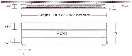
RC-3 with Both Side & Vertical Connections – Shown for Example Only
Panel Radiator Specification
|
|
BTUH/ft Ratings
| Energy efficient as well as space saving, RC panel radiators are true radiant panels. These panels provide more comfort at a lower room temperature than convective heaters. Various average water temperatures (AWT) are included here for your convenience, but for more specific conditions use the appropriate correction factor with the 215°F rating. Please see the technical pages for the correction factor best suited to the design conditions. |
|
||||||||||||||||||||||||||||||||||||||||||||||||||||||||||||||||||
Heating Capacity
Model Type RC
BTUH/ft Ratings
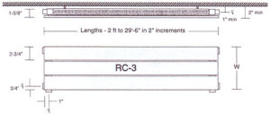
RC-3 with Both Side & Vertical Connections – Shown for Example Only
Technical Data For All RC Models Is Included Below
| MODEL TYPE |
HEIGHT H |
BTUH/FT OUTPUT @ LISTED AWT & 65°F EAT | DRY WT lbs/ft |
||||||||
| 215°F | 190 | 180 | 170 | 160 | 150 | 140 | 130 | 120 | |||
| RC-1 | 2-3/4″ | 144 | 113 | 101 | 90 | 79 | 68 | 58 | 48 | 39 | 1.3 |
| RC-2 | 5-3/4″ | 271 | 213 | 191 | 169 | 149 | 1219 | 109 | 91 | 73 | 2.4 |
| RC-3 | 8-5/8″ | 401 | 315 | 282 | 250 | 220 | 190 | 162 | 134 | 108 | 3.5 |
| RC-4 | 11-1/2″ | 528 | 415 | 372 | 330 | 290 | 251 | 213 | 177 | 142 | 4.6 |
| RC-5 | 14-3/8″ | 659 | 517 | 464 | 412 | 362 | 313 | 266 | 220 | 177 | 5.7 |
| RC-6 | 17-1/4″ | 795 | 624 | 559 | 496 | 436 | 377 | 320 | 266 | 213 | 6.8 |
| RC-7 | 20-1/4″ | 932 | 731 | 656 | 582 | 511 | 442 | 375 | 311 | 250 | 8.0 |
| RC-8 | 23-1/8″ | 1067 | 837 | 751 | 667 | 585 | 506 | 430 | 357 | 287 | 9.1 |
| RC-9 | 26-1/8″ | 1203 | 944 | 847 | 752 | 660 | 571 | 485 | 402 | 323 | 10.2 |
| RC-10 | 29″ | 1340 | 1052 | 943 | 837 | 735 | 636 | 540 | 448 | 360 | 11.3 |
| RC-11 | 31-7/8″ | 1477 | 1159 | 1039 | 923 | 810 | 700 | 595 | 494 | 397 | 12.4 |
| RC-12 | 34-7/8″ | 1613 | 1266 | 1135 | 1008 | 885 | 765 | 650 | 539 | 433 | 13.5 |
| RC-13 | 37-3/4″ | 1750 | 1373 | 1232 | 1093 | 960 | 830 | 705 | 585 | 470 | 14.6 |
| RC-14 | 40-5/8″ | 1886 | 1480 | 1327 | 1178 | 1035 | 895 | 760 | 631 | 507 | 15.7 |
| RC-15 | 43-5/8″ | 2022 | 1586 | 1423 | 1263 | 1109 | 959 | 814 | 676 | 543 | 16.8 |
| RC-16 | 46-1/2″ | 2158 | 1693 | 1519 | 1348 | 1184 | 1023 | 869 | 721 | 580 | 17.9 |
| RC-17 | 49-3/8″ | 2293 | 1800 | 1614 | 1433 | 1258 | 1088 | 924 | 767 | 616 | 19.0 |
| RC-18 | 52-3/8″ | 2429 | 1907 | 1710 | 1518 | 1333 | 1152 | 979 | 812 | 653 | 20.1 |
| RC-19 | 55-1/4″ | 2566 | 2013 | 1806 | 1603 | 1408 | 1217 | 1034 | 858 | 689 | 21.3 |
| RC-20 | 58-1/8″ | 2700 | 2119 | 1901 | 1687 | 1481 | 1281 | 1088 | 903 | 725 | 22.4 |
| RC-21 | 61″ | 2837 | 2226 | 1996 | 1772 | 1556 | 1345 | 1143 | 948 | 762 | 23.5 |
| RC-22 | 64″ | 2971 | 2332 | 2091 | 1856 | 1630 | 1409 | 1197 | 993 | 798 | 24.6 |
| RC-23 | 66-7/8″ | 3107 | 2438 | 2187 | 1941 | 1704 | 1474 | 1252 | 1039 | 834 | 25.7 |
| RC-24 | 69-3/4″ | 3238 | 2541 | 2279 | 2023 | 1776 | 1536 | 1305 | 1083 | 870 | 26.8 |
NOTE: Heat Outputs for various AWT’s include 15% Heat Effect for placement along outside walls. Use the 215° F Output Rating with the Correction Factor for more specific design conditions. High Pressure increases Dry Weight by 15%
Correction Factors
Correction Factors
| EAT | |||||||||||
| AWT | 45°F | 50°F | 55°F | 60°F | 65°F | 70°F | 75°F | 80°F | 85°F | 90°F | 95°F |
| 240°F | 1.365 | 1.350 | 1.304 | 1.266 | 1.220 | 1.171 | 1.124 | 1.086 | 1.039 | 1 | 0.953 |
| 235°F | 1.343 | 1.305 | 1.267 | 1.219 | 1.171 | 1.124 | 1.086 | 1.038 | 1 | 0.952 | 0.910 |
| 230°F | 1.305 | 1.267 | 1.219 | 1.171 | 1.124 | 1.086 | 1.038 | 1 | 0.952 | 0.910 | 0.868 |
| 225°F | 1.267 | 1.219 | 1.171 | 1.124 | 1.086 | 1.038 | 1 | 0.952 | 0.910 | 0.868 | 0.826 |
| 220°F | 1.219 | 1.171 | 1.124 | 1.086 | 1.038 | 1 | 0.952 | 0.910 | 0.868 | 0.826 | 0.785 |
| 215°F | 1.171 | 1.124 | 1.086 | 1.038 | 1 | 0.952 | 0.910 | 0.868 | 0.826 | 0.785 | 0.744 |
| 210°F | 1.124 | 1.086 | 1.038 | 1 | 0.952 | 0.910 | 0.868 | 0.826 | 0.785 | 0.744 | 0.704 |
| 205°F | 1.086 | 1.038 | 1 | 0.952 | 0.910 | 0.868 | 0.826 | 0.785 | 0.744 | 0.704 | 0.664 |
| 200°F | 1.038 | 1 | 0.952 | 0.910 | 0.868 | 0.826 | 0.785 | 0.744 | 0.704 | 0.664 | 0.625 |
| 195°F | 1 | 0.952 | 0.910 | 0.868 | 0.826 | 0.785 | 0.744 | 0.704 | 0.664 | 0.625 | 0.587 |
| 190°F | 0.952 | 0.910 | 0.868 | 0.826 | 0.785 | 0.744 | 0.704 | 0.664 | 0.625 | 0.587 | 0.549 |
| 185°F | 0.910 | 0.868 | 0.826 | 0.785 | 0.744 | 0.704 | 0.664 | 0.625 | 0.587 | 0.549 | 0.511 |
| 180°F | 0.868 | 0.826 | 0.785 | 0.744 | 0.704 | 0.664 | 0.625 | 0.587 | 0.549 | 0.511 | 0.474 |
| 175°F | 0.826 | 0.785 | 0.744 | 0.704 | 0.664 | 0.625 | 0.587 | 0.549 | 0.511 | 0.474 | 0.438 |
| 170°F | 0.785 | 0.744 | 0.704 | 0.664 | 0.625 | 0.587 | 0.549 | 0.511 | 0.474 | 0.438 | 0.403 |
| 165°F | 0.744 | 0.704 | 0.664 | 0.625 | 0.587 | 0.549 | 0.511 | 0.474 | 0.438 | 0.403 | 0.369 |
| 160°F | 0.704 | 0.664 | 0.625 | 0.587 | 0.549 | 0.511 | 0.474 | 0.438 | 0.403 | 0.369 | 0.334 |
| 155°F | 0.664 | 0.625 | 0.587 | 0.549 | 0.511 | 0.474 | 0.438 | 0.403 | 0.369 | 0.334 | 0.301 |
| 150°F | 0.625 | 0.587 | 0.549 | 0.511 | 0.474 | 0.438 | 0.403 | 0.369 | 0.334 | 0.301 | 0.269 |
| 145°F | 0.587 | 0.549 | 0.511 | 0.474 | 0.438 | 0.403 | 0.369 | 0.334 | 0.301 | 0.269 | 0.237 |
| 140°F | 0.549 | 0.511 | 0.474 | 0.438 | 0.403 | 0.369 | 0.334 | 0.301 | 0.269 | 0.237 | 0.207 |
| 135°F | 0.511 | 0.474 | 0.438 | 0.403 | 0.369 | 0.334 | 0.301 | 0.269 | 0.237 | 0.207 | 0.177 |
| 130°F | 0.474 | 0.438 | 0.403 | 0.369 | 0.334 | 0.301 | 0.269 | 0.237 | 0.207 | 0.177 | 0.149 |
| 125°F | 0.438 | 0.403 | 0.369 | 0.334 | 0.301 | 0.269 | 0.237 | 0.207 | 0.177 | 0.149 | 0.122 |
| 120°F | 0.403 | 0.369 | 0.334 | 0.301 | 0.269 | 0.237 | 0.207 | 0.177 | 0.149 | 0.122 | 0.096 |
| 115°F | 0.369 | 0.334 | 0.301 | 0.269 | 0.237 | 0.207 | 0.177 | 0.149 | 0.122 | 0.096 | 0.071 |
| 110°F | 0.334 | 0.301 | 0.269 | 0.237 | 0.207 | 0.177 | 0.149 | 0.122 | 0.096 | 0.071 | 0.50 |
| 105°F | 0.301 | 0.269 | 0.237 | 0.207 | 0.177 | 0.149 | 0.122 | 0.096 | 0.071 | 0.50 | 0.030 |
| 100°F | 0.269 | 0.237 | 0.207 | 0.177 | 0.149 | 0.122 | 0.096 | 0.071 | 0.50 | 0.030 | 0.011 |
| EXAMPLE: | To find the BTUH/ft Rating for an RF-4 Panel at 145°F AWT and 65°F EAT, Multiply the Correction Factor (0.438) by the BTUH/ft Rating at 215°F (1351), e.g. (0.438) X (1351) = 592 BTUH/ft |
Flow Rates
How To Determine Flow Rates
The flow rate through a Runtal radiator (or series of radiators) is dependent on the length of the radiator (or combined length of the radiator series), and the design Entering Water Temperature (EWT) and the design Leaving Water Temperature (LWT).
The designer picks the design EWT and LWT. For example, he might pick 170°F as the EWT and 150°F as the LWT. The median point between these two temperatures is called the Average Water Temperature (AWT), and in this example the AWT is 160°F.
The Runtal Heating Capacity charts are based on the heating capacity per foot of radiator, based on the designer’s chosen AWT, and this heating capacity per foot is expressed in units of BTUH/FT @ a given AWT. The required flow rate (GPM) is figured as follows:
Flow Rate = (Heating Capacity/Foot X Radiator Length)
DT –LWT) X 500]
The (EWT – LWT) is commonly referred to as the “Delta T”, or “DT”.
Therefore, our Flow Rate formula becomes:
GPM = (BTUH/FT X FT of Radiator) DT (DT X 500)
As an example, let’s say our designer needs 445 BTUH/FT capacity, over a
10′-0″ span of wall, and has chosen the design water temperatures as EWT = 170°F, and LWT = 150°F. This means our AWT is 160°F. Looking in the Runtal type “R” radiator Heating Capacity chart, we see that an R-4 radiator gives us the required 445 BTUH/FT at 160°F AWT. Therefore, the required flow rate for the 10′-0″ long R-4 radiator is:
GPM = (445 BTUH/FT X 10FT) DT (20°F DT X 500) = 0.445 GPM
Note that there are various combinations of EWT and LWT that can result in the same AWT. In our example above, for instance, a 180°F EWT and a 140°F LWT result in the same 160°F AWT. With Runtal’s unique flattened water tube design, Delta T’s of up to 60°F are possible without concern that the flow rate is too low for heat transfer.
As for a maximum flow rate for Runtal radiators, we recommend no more that 1.5 GPM per water tube. For our R-4 example above, this would mean a maximum flow rate of 6 GPM for an opposite end piped radiator, or 3 GPM for a same end piped radiator.
Piping Options
Piping Options
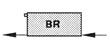
A Type Connections
|
B Type Connections
|
||||||||||
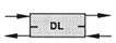
C Type Connections
|
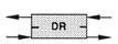
D Type Connections
|
||||||||||
Opposite End Series
|
|||||||||||
Same End Series
|
|||||||||||


Pressure Drop: Opposite End Piping
Model Type RC
Pressure Drop: Opposite End
RADIATOR PRESSURE DROP – FOOT OF HEAD PER RADIATOR
![]()
|
RADIATOR MODEL |
CONNECTION PD PER CONNECTION |
|
STD |
RF-1 | RF-2 | RF-3 | RF-4 | RF-5 | RF-6 | RF-7 | RF-8 | RF-9 | RF-10 | 1/2″ CONN PD |
|
| 1 | 2 | 3 | 4 | 5 | 6 | 7 | 8 | 9 | 10 | |||
| 0.05 | 0.21 | 0.05 | 0.02 | 0.01 | 0.01 | 0.01 | 0.00 | 0.00 | 0.00 | 0.00 | 0.01 | |
| 0.75 | 0.45 | 0.12 | 0.05 | 0.03 | 0.02 | 0.01 | 0.01 | 0.01 | 0.01 | 0.01 | 0.01 | |
| 1.00 | 0.79 | 0.21 | 0.09 | 0.05 | 0.04 | 0.02 | 0.02 | 0.01 | 0.01 | 0.01 | 0.03 | |
| 1.50 | 1.72 | 0.45 | 0.21 | 0.12 | 0.08 | 0.05 | 0.04 | 0.03 | 0.02 | 0.02 | 0.04 | |
| 2.00 | 3.00 | 0.79 | 0.36 | 0.21 | 0.13 | 0.09 | 0.07 | 0.05 | 0.04 | 0.04 | 0.06 | |
| 2.50 | 461 | 1.21 | 0.55 | 0.32 | 0.21 | 0.15 | 0.11 | 0.08 | 007 | 0.05 | 0.08 | |
| 3.00 | 6.56 | 1.72 | 0.79 | 0.45 | 0.29 | 0.21 | 0.15 | 0.12 | 0.09 | 0.08 | 0.10 | |
| 3.50 | 8.83 | 2.32 | 1.06 | 0.61 | 0.40 | 0.28 | 0.21 | 0.16 | 0.13 | 0.10 | 0.15 | |
|
GPM |
4.00 | 11.42 | 3.00 | 1.37 | 0.79 | 0.51 | 0.36 | 0.27 | 0.21 | 0.16 | 0.13 | 0.18 |
| 4.50 | 14.34 | 3.76 | 1.72 | 0.99 | 0.64 | 0.45 | 0.34 | 0.26 | 0.21 | 0.17 | 0.20 | |
| 5.00 | 17.57 | 4.61 | 2.11 | 1.21 | 0.79 | 0.55 | 0.41 | 0.32 | 0.25 | 0.21 | 0.25 | |
| 5.50 | 21.12 | 5.54 | 2.53 | 1.45 | 0.95 | 0.67 | 0.49 | 0.38 | 0.30 | 0.25 | 0.28 | |
| 6.00 | 24.98 | 6.56 | 3.00 | 1.72 | 1.12 | 0.79 | 0.58 | 0.45 | 0.36 | 0.29 | 0.33 | |
| 6.50 | 29.15 | 7.65 | 3.50 | 2.01 | 1.31 | 0.92 | 0.68 | 0.53 | 0.42 | 0.34 | 0.37 | |
| 7.00 | 33.64 | 8.83 | 4.04 | 2.32 | 1.51 | 1.06 | 0.79 | 0.61 | 0.48 | 0.40 | 0.42 | |
| 7.50 | 38.43 | 10.08 | 4.61 | 2.65 | 1.72 | 1.21 | 0.90 | 0.69 | 0.55 | 0.45 | 0.50 | |
| 8.00 | 43.52 | 11.42 | 5.22 | 3.00 | 1.95 | 1.37 | 1.02 | 0.79 | 0.63 | 0.51 | 0.56 | |
| MED PRESSURE TUBE |
||||||||||||
| 0.05 | 0.46 | 0.12 | 0.06 | 0.03 | 0.02 | 0.01 | 0.01 | 0.01 | 0.01 | 0.01 | 0.01 | |
| 0.75 | 1.00 | 0.26 | 0.12 | 0.07 | 0.04 | 0.03 | 0.02 | 0.02 | 0.01 | 0.01 | 0.01 | |
| 1.00 | 1.75 | 0.46 | 0.21 | 0.12 | 0.08 | 0.06 | 0.04 | 0.03 | 0.03 | 0.02 | 0.03 | |
| 1.50 | 3.83 | 1.00 | 0.46 | 0.26 | 0.17 | 0.12 | 0.09 | 0.07 | 0.06 | 0.04 | 0.04 | |
| 2.00 | 6.67 | 1.75 | 0.80 | 0.46 | 0.30 | 0.21 | 0.16 | 0.12 | 0.10 | 0.08 | 0.06 | |
| 2.50 | 10.26 | 2.69 | 1.23 | 0.71 | 0.46 | 0.32 | 0.24 | 0.19 | 0.15 | 0.12 | 0.08 | |
| 3.00 | 14.59 | 3.83 | 1.75 | 1.00 | 0.65 | 0.46 | 0.34 | 0.26 | 0.21 | 0.17 | 0.10 | |
| 3.50 | 19.65 | 5.16 | 2.36 | 1.35 | 0.88 | 0.62 | 0.46 | 0.36 | .28 | 0.23 | 0.15 | |
|
GPM |
4.00 | 25.42 | 6.67 | 3.05 | 1.75 | 1.14 | 0.80 | 0.59 | 0.46 | 0.37 | 0.30 | 0.18 |
| 4.50 | 31.91 | 8.37 | 3.83 | 2.20 | 1.43 | 1.00 | 0.75 | 0.58 | 0.46 | 0.37 | 0.20 | |
| 5.00 | 39.10 | 10.26 | 4.69 | 2.69 | 1.75 | 1.23 | 0.91 | 0.71 | 0.56 | 0.46 | 0.25 | |
| 5.50 | 47.00 | 12.33 | 5.64 | 3.24 | 2.10 | 1.48 | 1.10 | 0.85 | 0.68 | 0.55 | 0.28 | |
| 6.00 | 55.60 | 14.59 | 6.67 | 3.83 | 2.49 | 1.75 | 1.30 | 1.00 | 0.80 | 0.65 | 0.33 | |
| 6.50 | 64.88 | 17.03 | 7.79 | 4.47 | 2.90 | 2.04 | 1.52 | 1.17 | 0.93 | 0.76 | 0.37 | |
| 7.00 | 74.86 | 19.65 | 8.98 | 5.16 | 3.35 | 2.36 | 1.75 | 1.35 | 1.08 | 0.88 | 0.42 | |
| 7.50 | 85.52 | 22.44 | 10.26 | 5.89 | 3.83 | 2.69 | 2.00 | 1.55 | 1.23 | 1.00 | 0.50 | |
| 8.00 | 96.87 | 25.42 | 11.62 | 6.67 | 4.34 | 3.05 | 2.27 | 1.75 | 1.39 | 1.14 | 0.56 | |
| HIGH PRESSURE TUBE |
||||||||||||
| 0.50 | 0.82 | 0.22 | 0.10 | 0.06 | 0.04 | 0.03 | 0.02 | 0.01 | 0.01 | 0.01 | 0.01 | |
| 0.75 | 1.79 | 0.47 | 0.22 | 0.12 | 0.08 | 0.06 | 0.04 | 0.03 | 0.03 | 0.02 | 0.01 | |
| 1.00 | 3.13 | 0.82 | 0.38 | 0.22 | 0.14 | 0.10 | 0.07 | 0.06 | 0.05 | 0.04 | 0.03 | |
| 1.50 | 6.84 | 1.79 | 0.82 | 0.47 | 0.31 | 0.22 | 0.16 | 0.12 | 0.10 | 0.08 | 0.04 | |
| 2.00 | 11.91 | 3.13 | 1.43 | 0.82 | 0.53 | 0.38 | 0.28 | 0.22 | 0.17 | 0.14 | 0.06 | |
| 2.50 | 18.33 | 4.81 | 2.20 | 1.26 | 0.82 | 0.58 | 0.43 | 0.33 | 0.26 | 0.22 | 0.08 | |
| 3.00 | 26.06 | 6.84 | 3.13 | 1.79 | 1.17 | 0.82 | 0.61 | 0.47 | 0.38 | 0.31 | 0.10 | |
| 3.50 | 35.09 | 9.21 | 4.21 | 2.42 | 1.57 | 1.10 | 0.82 | 0.63 | 0.51 | 0.41 | 0.15 | |
|
GPM |
4.00 | 45.40 | 11.91 | 5.45 | 3.13 | 2.03 | 1.43 | 1.06 | 0.82 | 0.65 | 0.53 | 0.18 |
| 4.50 | 56.99 | 14.96 | 6.84 | 3.92 | 2.55 | 1.79 | 1.33 | 1.03 | 0.82 | 0.67 | 0.20 | |
| 5.00 | 69.84 | 18.33 | 8.38 | 4.81 | 3.13 | 2.20 | 1.63 | 1.26 | 1.01 | 0.82 | 0.25 | |
| 5.50 | 83.95 | 22.03 | 10.07 | 5.78 | 3.76 | 2.64 | 1.96 | 1.52 | 1.21 | 0.99 | 0.28 | |
| 6.00 | 99.30 | 26.06 | 11.91 | 6.84 | 4.45 | 3.13 | 2.32 | 1.79 | 1.43 | 1.17 | 0.33 | |
| 6.50 | 115.88 | 30.41 | 13.91 | 7.98 | 5.19 | 3.65 | 2.71 | 2.09 | 1.67 | 1.36 | 0.37 | |
| 7.00 | 133.70 | 35.09 | 16.04 | 9.21 | 5.99 | 4.21 | 3.13 | 2.42 | 1.93 | 1.57 | 0.42 | |
| 7.50 | 152.74 | 40.08 | 18.33 | 10.52 | 6.84 | 4.81 | 3.57 | 2.76 | 2.20 | 1.79 | 0.50 | |
| 8.00 | 173.01 | 45.40 | 20.76 | 11.91 | 7.75 | 5.45 | 4.05 | 3.13 | 2.49 | 2.03 | 0.56 | |
RADIATOR PRESSURE DROP IS FOR THE ENTIRE RADIATOR; IT IS NOT PER FOOT OF RADIATOR
CONNECTION PRESSURE DROP FOR THE 3/4″ CONNECTION IS THE SAME AS THE 1/2″ CONNECTION
Pressure Drop: Same End Piping
Model Type RC
Pressure Drop: Same End
RADIATOR PRESSURE DROP – FOOT OF HEAD PER RADIATOR
![]()
|
RADIATOR MODEL |
CONNECTION PD PER CONNECTION |
|
STD |
RC-2 | RC-4 | RC-6 | RC-8 | RC-10 | RC-12 | RC-14 | RC-16 | RC-18 | RC-20 | 1/2″ CONN PD |
|
| RC-3 | RC-5 | RC-7 | RC-9 | RC-11 | RC-13 | RC-15 | RC-17 | RC-19 | RC-21 | |||
| 1 | 2 | 3 | 4 | 5 | 6 | 7 | 4 | 4 | 5 | |||
| 0.05 | 0.21 | 0.05 | 0.02 | 0.01 | 0.01 | 0.01 | 0.00 | 0.01 | 0.01 | 0.01 | 0.01 | |
| 0.75 | 0.45 | 0.12 | 0.05 | 0.03 | 0.02 | 0.01 | 0.01 | 0.03 | 0.03 | 0.02 | 0.01 | |
| 1.00 | 0.79 | 0.21 | 0.09 | 0.05 | 0.04 | 0.02 | 0.02 | 0.05 | 0.05 | 0.04 | 0.03 | |
| 1.50 | 1.72 | 0.45 | 0.21 | 0.12 | 0.08 | 0.05 | 0.04 | 0.12 | 0.12 | 0.08 | 0.04 | |
| 2.00 | 3.00 | 0.79 | 0.36 | 0.21 | 0.13 | 0.09 | 0.07 | 0.21 | 0.21 | 0.13 | 0.06 | |
| 2.50 | 4.61 | 1.21 | 0.55 | 0.32 | 0.21 | 0.15 | 0.11 | 0.32 | 0.32 | 0.21 | 0.08 | |
| 3.00 | 6.56 | 1.72 | 0.79 | 0.45 | 0.29 | 0.21 | 0.15 | 0.45 | 0.45 | 0.29 | 0.10 | |
| 3.50 | 8.83 | 2.32 | 1.06 | 0.61 | 0.40 | 0.28 | 0.21 | 0.61 | 0.61 | 0.40 | 0.15 | |
|
GPM |
4.00 | 11.42 | 3.00 | 1.37 | 0.79 | 0.51 | 0.36 | 0.27 | 0.79 | 0.79 | 0.51 | 0.18 |
| 4.50 | 14.34 | 3.76 | 1.72 | 0.99 | 0.64 | 0.45 | 0.34 | 0.99 | 0.99 | 0.64 | 0.20 | |
| 5.00 | 1757 | 4.61 | 2.11 | 1.21 | 0.79 | 0.55 | 0.41 | 1.21 | 1.21 | 0.79 | 0.25 | |
| 5.50 | 21.12 | 5.54 | 2.53 | 1.45 | 0.95 | 0.67 | 0.49 | 1.45 | 1.45 | 0.95 | 0.28 | |
| 6.00 | 24.98 | 6.56 | 3.00 | 1.72 | 1.12 | 0.79 | 0.58 | 1.72 | 1.72 | 1.12 | 0.33 | |
| 6.50 | 29.15 | 7.65 | 3.50 | 2.01 | 1.31 | 0.92 | 0.68 | 2.01 | 2.01 | 1.31 | 0.37 | |
| 7.00 | 33.64 | 8.83 | 4.04 | 2.32 | 1.51 | 1.06 | 0.79 | 2.32 | 2.32 | 1.51 | 0.42 | |
| 7.50 | 38.43 | 10.08 | 4.61 | 2.65 | 1.72 | 1.21 | 0.90 | 2.65 | 2.65 | 1.72 | 0.50 | |
| 8.00 | 43.52 | 11.42 | 5.22 | 3.00 | 1.95 | 1.37 | 1.02 | 3.00 | 3.00 | 1.95 | 0.56 | |
| MED PRESSURE TUBE |
||||||||||||
| 0.05 | 0.46 | 0.12 | 0.06 | 0.03 | 0.02 | 0.01 | 0.01 | 0.03 | 0.03 | 0.02 | 0.01 | |
| 0.75 | 1.00 | 0.26 | 0.12 | 0.07 | 0.04 | 0.03 | 0.02 | 0.07 | 0.07 | 0.04 | 0.01 | |
| 1.00 | 1.75 | 0.46 | 0.21 | 0.12 | 0.06 | 0.06 | 0.04 | 0.12 | 0.12 | 0.08 | 0.03 | |
| 1.50 | 3.83 | 1.00 | 0.46 | 0.26 | 0.17 | 0.12 | 0.09 | 0.26 | 0.26 | 0.17 | 0.04 | |
| 2.00 | 6.67 | 1.75 | 0.80 | 0.46 | 0.30 | 0.21 | 0.16 | 0.46 | 0.46 | 0.30 | 0.06 | |
| 2.50 | 10.26 | 2.69 | 1.23 | 0.71 | 0.46 | 0.32 | 0.24 | 0.71 | 0.71 | 0.46 | 0.08 | |
| 3.00 | 14.59 | 3.83 | 1.75 | 1.00 | 0.65 | 0.46 | 0.34 | 1.00 | 1.00 | 0.65 | 0.10 | |
| 3.50 | 19.65 | 5.16 | 2.36 | 1.35 | 0.88 | 0.62 | 0.46 | 1.35 | 1.35 | 0.88 | 0.15 | |
|
GPM |
4.00 | 25.42 | 6.67 | 3.05 | 1.75 | 1.14 | 0.80 | 0.59 | 1.75 | 1.75 | 1.14 | 0.18 |
| 4.50 | 31.91 | 8.37 | 3.83 | 2.20 | 1.43 | 1.00 | 0.75 | 2.20 | 2.20 | 1.43 | 0.20 | |
| 5.00 | 39.10 | 10.26 | 4.69 | 2.69 | 1.75 | 1.23 | 0.91 | 2.69 | 2.69 | 1.75 | 0.25 | |
| 5.50 | 47.00 | 12.33 | 5.64 | 3.24 | 2.10 | 1.48 | 1.10 | 3.24 | 3.24 | 2.10 | 0.28 | |
| 6.00 | 55.60 | 14.59 | 6.67 | 3.83 | 2.49 | 1.75 | 1.30 | 3.83 | 3.83 | 2.49 | 0.33 | |
| 6.50 | 64.88 | 17.03 | 7.79 | 4.47 | 2.90 | 2.04 | 1.52 | 4.47 | 4.47 | 2.90 | 0.37 | |
| 7.00 | 74.86 | 19.65 | 8.98 | 5.16 | 3.35 | 2.36 | 1.75 | 5.16 | 5.16 | 3.35 | 0.42 | |
| 7.50 | 85.52 | 22.44 | 10.26 | 5.89 | 3.83 | 2.69 | 2.00 | 5.89 | 5.89 | 3.83 | 0.50 | |
| 8.00 | 96.87 | 25.42 | 11.62 | 6.67 | 4.34 | 3.05 | 2.27 | 6.67 | 6.67 | 4.34 | 0.56 | |
| HIGH PRESSURE TUBE |
||||||||||||
| 0.50 | 0.82 | 0.22 | 0.10 | 0.06 | 0.04 | 0.03 | 0.02 | 0.06 | 0.06 | 0.04 | 0.01 | |
| 0.75 | 1.79 | 0.47 | 0.22 | 0.12 | 0.08 | 0.06 | 0.04 | 0.12 | 0.12 | 0.08 | 0.01 | |
| 1.00 | 3.13 | 0.82 | 0.38 | 0.22 | 0.14 | 0.10 | 0.07 | 0.22 | 0.22 | 0.14 | 0.03 | |
| 1.50 | 6.84 | 1.79 | 0.82 | 0.47 | 0.31 | 0.22 | 0.16 | 0.47 | 0.47 | 0.31 | 0.04 | |
| 2.00 | 11.91 | 3.13 | 1.43 | 0.82 | 0.53 | 0.38 | 0.28 | 0.82 | 0.82 | 0.53 | 0.06 | |
| 2.50 | 18.33 | 4.81 | 2.20 | 1.26 | 0.82 | 0.58 | 0.43 | 1.26 | 1.26 | 0.82 | 0.08 | |
| 3.00 | 26.06 | 6.84 | 3.13 | 1.79 | 1.17 | 0.82 | 0.61 | 1.79 | 1.79 | 1.17 | 0.10 | |
| 3.50 | 35.09 | 9.21 | 4.21 | 2.42 | 1.57 | 1.10 | 0.82 | 2.42 | 2.42 | 1.57 | 0.15 | |
|
GPM |
4.00 | 45.40 | 11.91 | 5.45 | 3.13 | 2.03 | 1.43 | 1.06 | 3.13 | 3.13 | 2.03 | 0.18 |
| 4.50 | 56.99 | 14.96 | 6.84 | 3.92 | 2.55 | 1.79 | 1.33 | 3.92 | 3.92 | 2.55 | 0.20 | |
| 5.00 | 69.84 | 18.33 | 8.38 | 4.81 | 3.13 | 2.20 | 1.63 | 4.81 | 4.81 | 3.13 | 0.25 | |
| 5.50 | 83.95 | 22.03 | 10.07 | 5.78 | 3.76 | 2.64 | 1.96 | 5.78 | 5.78 | 3.76 | 0.28 | |
| 6.00 | 99.30 | 26.06 | 11.91 | 6.84 | 4.45 | 3.13 | 2.32 | 6.84 | 6.84 | 4.45 | 0.33 | |
| 6.50 | 115.88 | 30.41 | 13.91 | 7.98 | 5.19 | 3.65 | 2.71 | 7.98 | 7.98 | 5.19 | 0.37 | |
| 7.00 | 133.70 | 35.09 | 16.04 | 9.21 | 5.99 | 4.21 | 3.13 | 9.21 | 9.21 | 5.99 | 0.42 | |
| 7.50 | 152.74 | 40.08 | 18.33 | 10.52 | 6.84 | 4.81 | 3.57 | 10.52 | 10.52 | 6.84 | 0.50 | |
| 8.00 | 173.01 | 45.40 | 20.76 | 11.91 | 7.75 | 5.45 | 4.05 | 11.91 | 11.91 | 7.75 | 0.56 | |
RADIATOR PRESSURE DROP IS FOR THE ENTIRE RADIATOR; IT IS NOT PER FOOT OF RADIATOR
CONNECTION PRESSURE DROP FOR THE 3/4″ CONNECTION IS THE SAME AS THE 1/2″ CONNECTION
Pressure Ratings
Pressure ratings for the radiation shall be as follows:
STANDARD: Working pressure-56 PSI maximum, Test Pressure-74 PSI maximum
HIGH: Working pressure-128 PSI maximum, Test Pressure 184 PSI maximum
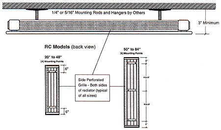
Mounting Systems
 |
RC panels are ceiling mounted with threaded rod, nuts and ceiling supports, which are supplied by others. Please see the RC technical pages for more complete mounting details. |
Ceiling Mounting
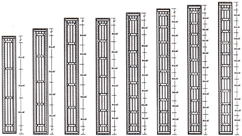
Model Type RC
Ceiling Mounting
| 86″ to 118″ [8] Mounting Points |
120″ to 152″ [10] Mounting Points |
154″ to 188″ [12] Mounting Points |
190″ to 222″ [14] Mounting Points |
224″ to 258″ [16] Mounting Points |
260″ to 290″ [18] Mounting Points |
292″ to 326″ [20] Mounting Points |
328″ to 354″ [22] Mounting Points |
 |
Valves & Flex Connections
Warranty
All Runtal radiators are covered by a 5-Year Limited Warranty.
Colors & Finishes
The panel radiation shall be cleaned and phosphatized in preparation for the powder coat finish. The radiation is then finish painted with a gloss powder coat finish, for a total paint thickness of 2-3 mils (0.002” – 0.003”). The color shall be selected from Runtal’s ten Standard Colors; or Runtal Optional Colors shall be available at and additional cost.
Radiator Installation Instructions
Radiator Installation Instructions
Vertical & Ceiling Radiators
GENERAL NOTES – BOTH STYLES
Radiators are boxed together in as few crates as possible. A box of brackets is included as a separate piece, and it is marked to denote brackets. Inside the crates, each panel is wrapped in foam sheeting. Saving this foam to re-wrap the panel once it is wall mounted will protect it from construction site damage.
Each radiator is tagged with a label that indicates the project name, model type, color, connection code, bracket type & quantity and tag number. The tag number will usually designate a floor level and room number for easier placement on the job. Locate each radiator as required.
VERTICALLY MOUNTED RV RADIATORS
Carefully place each radiator face down on a smooth level surface (e.g. floor or table). Distribute the K11 wall brackets for each radiator. The tag on the radiator indicates the quantity of brackets. Mount the brackets securely on wall studs or solid backing, spacing them to match the horizontal wall mounting bars on the back side of the RV panel. There will be (2) K11 brackets per horizontal mounting bar. Make sure to mount the K11’s in far enough to avoid contact with the side perforated grille.
Allow a minimum of 3 inches below each panel radiator to facilitate cleaning and to assure proper output.
CEILING MOUNTED RC RADIATORS
RC model ceiling radiators do not come with any mounting brackets. Typically, installers use threaded rod with locking nuts to secure the panel to the ceiling structure. There are two mounting holes per cross-member stiffener on the back side of the radiator. Each of these mounting points should be used to suspend the radiator, to avoid sagging. It is typically easier to attach the threaded rods to the radiator before raising the assembly to the ceiling for final mounting. Once the radiator is securely fastened to the ceiling structure, adjust the nuts on the threaded rod to straighten and level the radiator. It is recommended to have at least 3 inches minimum from the face of the radiator to the finished ceiling above it. In cases where upward radiation from the back side of the radiator is undesirable, foil faced insulation can be placed in the cavities created by the perforated steel side channels.
ADDITIONAL INSTALLATION NOTES – BOTH STYLES
Thread the supply and return fitting into the connections on the radiator. The sealing tape or pipe dope used is the installer’s choice – make sure the connections are leak tight. One quarter turn past hand tight is usually sufficient. Each radiator needs to be fitted with a 1/8” air vent prior to startup.
Once the radiators are installed, the system can be tested to 50 psi. DO NOT OVER-PRESSURIZE THE RADIATORS as permanent damage may be done.
Standard Pressure Panels – Maximum 56 psi
High Pressure Panels – Maximum 128 psi
Radiators expand a maximum of 0.016 inch per linear foot of length if heated to 215°F. Piping attached to the radiator must provide the necessary expansion compensation.
When the system has been shown to hold 50 psi maximum air, the piping and radiators can be filled with water. As water fills the system and radiators, air is forced to the vent fittings. Vent as much air as possible before turning on the circulating pump(s).
With the system is filled, operate the circulator(s) to force the remaining air to the high points of the system. Turn off the circulator(s) to vent the panels. Each radiator should be individually bled of air. Once cold venting has been completed, heat the system to design temperature and repeat the venting procedure as many times as necessary to remove all air from the system.
Operation & Maintenance
For R, RF, R2F, R3F, RV, RC, UFLT and ThermoTouch
Hydronic Radiator Operation
- Radiators are manufactured in the USA of cold rolled low carbon steel and should be used only in closed closed hydronic systems to assure no corrosion of any system components.
- Proper radiator operation depends on adequate flow of water to the panel, which can only be accomplished when all the system air has been fully vented from the panels.
- Radiators should each be vented, with the system pressurized but in a static state (pumps off). Venting may need to be done periodically to assure a closed system.
- DO NOT OVER-PRESSURIZE RADIATORS:
Most radiators are standard pressure construction. Standard pressure radiators should be tested with NO MORE THAN 50 PSI. - Radiator Operating Pressure Ratings:
Standard Pressure – 56 psi max (Tested at 74 psi)
High Pressure – 128 psi max (Tested at 184 psi) - Radiators expand a maximum of 0.016 inch per linear foot of length if heated to 215°F. Piping attached to the radiator must provide the necessary expansion compensation.
- Flexible piping and elbowed piping are two simple ways to provide the 1/8 inch to 1/2 inch (typical) of flexibility required in expansion situations (usually series piping).
- Runtal Radiators require less flow rate than other hydronic heating products. If flow noise is apparent, balance the system until the noise is reduced.
- For a delta T of 20°F. (T supply minus T return), divide the total Btu/hr capacity of the loop by 10,000. This gives the Flow Rate in gallons per minute (GPM)
- Many levels of control are available today for hydronic systems. Runtal Radiators will provide nice, even heating whether operated by a simple thermostat to baseboard loop system, or an advanced boiler reset controller with motorized mixing valves, constant circulation and 2-pipe distribution.
Radiator Maintenance
- Hydronic system maintenance should include routine checks for piping leaks (usually indicated by frequent makeup water), and a yearly diagnosis of the system water pH to evaluate its corrosive potential.
- Internal radiator maintenance depends entirely on the system water makeup and proper venting. Hydronic system additives are available to passivate and protect against freezing. These additives will not significantly reduce the output of Runtal Radiators.
- External radiator maintenance consists of keeping the surfaces clean, and any paint nicks or deep scratches painted with touch-up to prevent any surface rust.
- Radiators can be painted after sanding with fine grit paper to dull the high gloss and by wiping with solvent or a tack rag. Use only oil-based enamel paint (alkyd, acrylic, urethane, epoxy) – do not use latex or lacquer paint. Use urethane or epoxy enamel for radiators located in harsh environments. Spray the paint to achieve an even coating, and let dry completely before heating the radiator.
Product Specifications
General:
Provide steel panel radiator elements of lengths and in locations as indicated, and of capacities, style and having accessories as scheduled. The ceiling hung heating panel radiation shall be of one-piece all-welded steel construction, consisting of flattened water tubes welded to headers at each end. The radiator shall include an integral heavy gauge (0.09” minimum) all-welded perforated side grilles.
The radiator’s headers shall include all necessary inlet, outlet and vent connections as required. Standard connection sizes are ó” NPT tapered thread for supply and return piping, and 1/8” for the vent connection. Internal baffling is provided where required for proper water flow. Optional.” connections shall be available at an additional cost.
The radiant heating panels shall be available in lengths from 2’-0” to 29’-6” in two inch even increments without the need for splicing. Appropriate ceiling mounting (typically threaded rod) shall be provided by the installing contractor. Panel radiation expansion shall not exceed 1/64” per foot of radiation at 215ºF. The installer shall provide adequate expansion compensation for each radiator.
The panel radiation shall be manufactured in the USA.
Pressure Ratings:
Pressure ratings for the radiation shall be as follows:
STANDARD: Working pressure-56 PSI maximum, Test Pressure-74 PSI maximum
OR
HIGH: Working pressure-128 PSI maximum, Test Pressure 184 PSI maximum
Finishes:
The panel radiation shall be cleaned and phosphatized in preparation for the powder coat finish. The radiation is then finish painted with a gloss powder coat finish, for a total paint thickness of 2-3 mils (0.002” – 0.003”). The color shall be selected from Runtal’s ten Standard Colors; or Runtal Optional Colors shall be available at and additional cost.
Warranty:
All Runtal radiators are covered by a 5-Year Limited Warranty.
Manufacturer:
Subject to compliance with requirements, provide flat tube panel radiation as manufactured by Runtal North America, Inc.
OPTIONAL ITEMS WHICH MAY BE ADDED TO THE SPECIFICATION:
- Ribbed pipe cover trims, finished to match the radiators shall be provided with the radiation.
- The radiation manufacturer shall provide combination shutoff valve/union fitting of less than two inches in width for the supply and return to each panel radiator, to be field installed by others.
- Runtal-Flex connectors shall be used where appropriate to provide expansion compensation for the radiators.
BTUH/ft Ratings
Heating Capacity
Correction Factors
Flow Rates
How To Determine Flow Rates
The flow rate through a Runtal radiator (or series of radiators) is dependent on the length of the radiator (or combined length of the radiator series), and the design Entering Water Temperature (EWT) and the design Leaving Water Temperature (LWT).
The designer picks the design EWT and LWT. For example, he might pick 170°F as the EWT and 150°F as the LWT. The median point between these two temperatures is called the Average Water Temperature (AWT), and in this example the AWT is 160°F.
The Runtal Heating Capacity charts are based on the heating capacity per foot of radiator, based on the designer’s chosen AWT, and this heating capacity per foot is expressed in units of BTUH/FT @ a given AWT. The required flow rate (GPM) is figured as follows:
Flow Rate = (Heating Capacity/Foot X Radiator Length)
DT –LWT) X 500]
The (EWT – LWT) is commonly referred to as the “Delta T”, or “DT”.
Therefore, our Flow Rate formula becomes:
GPM = (BTUH/FT X FT of Radiator) DT (DT X 500)
As an example, let’s say our designer needs 445 BTUH/FT capacity, over a
10′-0″ span of wall, and has chosen the design water temperatures as EWT = 170°F, and LWT = 150°F. This means our AWT is 160°F. Looking in the Runtal type “R” radiator Heating Capacity chart, we see that an R-4 radiator gives us the required 445 BTUH/FT at 160°F AWT. Therefore, the required flow rate for the 10′-0″ long R-4 radiator is:
GPM = (445 BTUH/FT X 10FT) DT (20°F DT X 500) = 0.445 GPM
Note that there are various combinations of EWT and LWT that can result in the same AWT. In our example above, for instance, a 180°F EWT and a 140°F LWT result in the same 160°F AWT. With Runtal’s unique flattened water tube design, Delta T’s of up to 60°F are possible without concern that the flow rate is too low for heat transfer.
As for a maximum flow rate for Runtal radiators, we recommend no more that 1.5 GPM per water tube. For our R-4 example above, this would mean a maximum flow rate of 6 GPM for an opposite end piped radiator, or 3 GPM for a same end piped radiator.
Piping Options
Pressure Drop: Opposite End Piping
Pressure Drop: Same End Piping
Pressure Ratings
Pressure ratings for the radiation shall be as follows:
STANDARD: Working pressure-56 PSI maximum, Test Pressure-74 PSI maximum
HIGH: Working pressure-128 PSI maximum, Test Pressure 184 PSI maximum
Mounting Systems
Ceiling Mounting
Finishes
The panel radiation shall be cleaned and phosphatized in preparation for the powder coat finish. The radiation is then finish painted with a gloss powder coat finish, for a total paint thickness of 2-3 mils (0.002” – 0.003”). The color shall be selected from Runtal’s ten Standard Colors; or Runtal Optional Colors shall be available at and additional cost.
Valves & Flex Connections
Warranty
All Runtal radiators are covered by a 5-Year Limited Warranty.
Radiator Installation Instructions
Radiator Installation Instructions
Vertical & Ceiling Radiators
GENERAL NOTES – BOTH STYLES
Radiators are boxed together in as few crates as possible. A box of brackets is included as a separate piece, and it is marked to denote brackets. Inside the crates, each panel is wrapped in foam sheeting. Saving this foam to re-wrap the panel once it is wall mounted will protect it from construction site damage.
Each radiator is tagged with a label that indicates the project name, model type, color, connection code, bracket type & quantity and tag number. The tag number will usually designate a floor level and room number for easier placement on the job. Locate each radiator as required.
VERTICALLY MOUNTED RV RADIATORS
Carefully place each radiator face down on a smooth level surface (e.g. floor or table). Distribute the K11 wall brackets for each radiator. The tag on the radiator indicates the quantity of brackets. Mount the brackets securely on wall studs or solid backing, spacing them to match the horizontal wall mounting bars on the back side of the RV panel. There will be (2) K11 brackets per horizontal mounting bar. Make sure to mount the K11’s in far enough to avoid contact with the side perforated grille.
Allow a minimum of 3 inches below each panel radiator to facilitate cleaning and to assure proper output.
CEILING MOUNTED RC RADIATORS
RC model ceiling radiators do not come with any mounting brackets. Typically, installers use threaded rod with locking nuts to secure the panel to the ceiling structure. There are two mounting holes per cross-member stiffener on the back side of the radiator. Each of these mounting points should be used to suspend the radiator, to avoid sagging. It is typically easier to attach the threaded rods to the radiator before raising the assembly to the ceiling for final mounting. Once the radiator is securely fastened to the ceiling structure, adjust the nuts on the threaded rod to straighten and level the radiator. It is recommended to have at least 3 inches minimum from the face of the radiator to the finished ceiling above it. In cases where upward radiation from the back side of the radiator is undesirable, foil faced insulation can be placed in the cavities created by the perforated steel side channels.
ADDITIONAL INSTALLATION NOTES – BOTH STYLES
Thread the supply and return fitting into the connections on the radiator. The sealing tape or pipe dope used is the installer’s choice – make sure the connections are leak tight. One quarter turn past hand tight is usually sufficient. Each radiator needs to be fitted with a 1/8” air vent prior to startup.
Once the radiators are installed, the system can be tested to 50 psi. DO NOT OVER-PRESSURIZE THE RADIATORS as permanent damage may be done.
Standard Pressure Panels – Maximum 56 psi
High Pressure Panels – Maximum 128 psi
Radiators expand a maximum of 0.016 inch per linear foot of length if heated to 215°F. Piping attached to the radiator must provide the necessary expansion compensation.
When the system has been shown to hold 50 psi maximum air, the piping and radiators can be filled with water. As water fills the system and radiators, air is forced to the vent fittings. Vent as much air as possible before turning on the circulating pump(s).
With the system is filled, operate the circulator(s) to force the remaining air to the high points of the system. Turn off the circulator(s) to vent the panels. Each radiator should be individually bled of air. Once cold venting has been completed, heat the system to design temperature and repeat the venting procedure as many times as necessary to remove all air from the system.
Operation & Maintenance
For R, RF, R2F, R3F, RV, RC, UFLT and ThermoTouch
Hydronic Radiator Operation
- Radiators are manufactured in the USA of cold rolled low carbon steel and should be used only in closed closed hydronic systems to assure no corrosion of any system components.
- Proper radiator operation depends on adequate flow of water to the panel, which can only be accomplished when all the system air has been fully vented from the panels.
- Radiators should each be vented, with the system pressurized but in a static state (pumps off). Venting may need to be done periodically to assure a closed system.
- DO NOT OVER-PRESSURIZE RADIATORS:
Most radiators are standard pressure construction. Standard pressure radiators should be tested with NO MORE THAN 50 PSI. - Radiator Operating Pressure Ratings:
Standard Pressure – 56 psi max (Tested at 74 psi)
High Pressure – 128 psi max (Tested at 184 psi) - Radiators expand a maximum of 0.016 inch per linear foot of length if heated to 215°F. Piping attached to the radiator must provide the necessary expansion compensation.
- Flexible piping and elbowed piping are two simple ways to provide the 1/8 inch to 1/2 inch (typical) of flexibility required in expansion situations (usually series piping).
- Runtal Radiators require less flow rate than other hydronic heating products. If flow noise is apparent, balance the system until the noise is reduced.
- For a delta T of 20°F. (T supply minus T return), divide the total Btu/hr capacity of the loop by 10,000. This gives the Flow Rate in gallons per minute (GPM)
- Many levels of control are available today for hydronic systems. Runtal Radiators will provide nice, even heating whether operated by a simple thermostat to baseboard loop system, or an advanced boiler reset controller with motorized mixing valves, constant circulation and 2-pipe distribution.
Radiator Maintenance
- Hydronic system maintenance should include routine checks for piping leaks (usually indicated by frequent makeup water), and a yearly diagnosis of the system water pH to evaluate its corrosive potential.
- Internal radiator maintenance depends entirely on the system water makeup and proper venting. Hydronic system additives are available to passivate and protect against freezing. These additives will not significantly reduce the output of Runtal Radiators.
- External radiator maintenance consists of keeping the surfaces clean, and any paint nicks or deep scratches painted with touch-up to prevent any surface rust.
- Radiators can be painted after sanding with fine grit paper to dull the high gloss and by wiping with solvent or a tack rag. Use only oil-based enamel paint (alkyd, acrylic, urethane, epoxy) – do not use latex or lacquer paint. Use urethane or epoxy enamel for radiators located in harsh environments. Spray the paint to achieve an even coating, and let dry completely before heating the radiator.